

Latency
The March to Budget-Friendly vRAN Continues!

As with most of my recent blog posts, I’m here to share some exciting updates on the work that CableLabs has been doing in the Telecom Infra Project (TIP) with virtualized RAN for non-ideal transport networks—for example, DOCSIS networks, passive optical networks (PONs) and really anything not on dedicated fiber. Over the past 6 months or so, we’ve reached some milestones that are worth a blog post blast. I’m going to keep each update brief, but please follow the links to dig in further where you’re interested.
TIP vRAN Fronthaul White Paper #2
On November 13, TIP’s vRAN Fronthaul Project Group is releasing a white paper discussing the results of Phase 1 of the project. The paper covers the combined learnings from the four Community Lab efforts led by Airtel, BT, CableLabs and TIM. We also include some key takeaways with which operators can assess the network assets that can be used in future vRAN deployments. You can find the paper here.
TIP Summit vRAN Fronthaul Demo
Also this week, the vRAN Fronthaul team has assembled a demo for TIP Summit ’19 in Amsterdam. The demo is showing the newly containerized multi-vendor vRAN solution running two remote radios (RUs) from a single CU/DU virtual baseband unit. In the LTE software stack, the Layer 2 and 3 containers come from Altran, and the Layer 1 container comes from Phluido, with RUs from Benetel. The containerized setup increases CPU efficiency by over 80 percent relative to our previous virtual machine–based architecture. If you’re in Amsterdam at TIP Summit, be sure to stop by the vRAN stand on the show floor.
TIP vRAN Fronthaul Trial with Shaw Communications
In July of this year, Shaw Communications, CableLabs and TIP collaborated to trial the vRAN Fronthaul LTE solution from Altran, Benetel, and Phluido over the Shaw commercial grade DOCSIS networks. In a fantastic result, we were able to demonstrate the ability of the Shaw DOCSIS networks to support Option 7-2 split fronthaul traffic for LTE services. In addition, we replicated all of our lab findings over the Shaw DOCSIS networks, validating the ability of our lab results to transfer to real world networks. “The trial demonstrated that Shaw’s hybrid fibre coaxial FibrePlus network is well positioned to support not only existing wireless services but the significant densification coming with the deployment of 5G,” said Damian Poltz, Vice President, Technology Strategy and Networks, Shaw Communications.
O-RAN Specification Includes Non-Ideal Fronthaul
While the team was busy hitting all these milestones in the TIP vRAN Fronthaul project, during the first half of the year CableLabs also led a collaborative effort to bring non-ideal fronthaul support to the O-RAN Alliance CUS plane specification. As of July, the 2.0 version of the CUS plane specification now includes support for non-ideal fronthaul with latencies up to 30ms over a common Option 7-2 interface. In addition, a new appendix was added to provide further detail on the implementation and operational specifics of deploying the lower-layer split over non-ideal transport such as DOCSIS networks, PON or managed Ethernet.
You can find out more by clicking the link below.

Latency
CoMP over DOCSIS: Femtocells in the Age of vRAN

As promised in the last couple blogs discussing DOCSIS based femtocells, we’ve saved the best for last. So far in the series, we’ve made the case for femtocells over DOCSIS networks and laid out the total cost of ownership (TCO) benefits of this deployment model. In this final blog post, I’ll share the results of some testing we’ve been doing at CableLabs on using Coordinated Multipoint (CoMP) to optimize femtocell performance in dense deployments.
Decluttering the Radio Signal
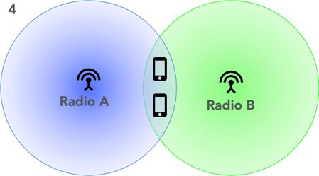
Let’s step back and look at a key issue that has limited the benefit of femtocells in the past: intercell interference. When femtocells (or any cells, for that matter) are placed in close proximity, the radio signals each cell site produces can bleed into its neighbor’s territory and negatively affect network performance.
With CoMP, neighboring cells can coordinate their transmissions in a variety of ways to work collaboratively and prevent interference. They can share scheduling and beamforming data to avoid creating interference. Or, they can use joint processing, which allows multiple cells to talk to a single cell phone at the same time, increasing the signal quality.
Although it’s not a perfect analogy, it’s a bit like trying to listen to a bunch of people singing their favorite song at the top of their lungs versus listening to a choir following a conductor, as you see in the following figure. The former is old femtocells, and the latter is virtualized RAN (vRAN) femtocells using CoMP.

Icons made by Freepik from Flaticon is licensed by CC 3.0 BY.
Since its inception, CoMP has been largely believed to require fiber transport links to work. For example, in TR 36.819, there’s a whole section devoted to the impact of “higher latency communication between points,” where “higher” refers to 5ms, 10ms or 15ms of latency. In that text, gains decrease as latency increases, ultimately going negative (i.e., losses in performance).
However, with the increase in attention on vRAN, particularly lower-layer splits like the work going on in Telecom Infra Project (TIP) vRAN Fronthaul and O-RAN Alliance WG4, latency takes on new meanings with respect to CoMP.
For example, what matters more, the latency from one radio unit to another or the latency from one virtualized baseband unit (vBBU) to another? And if it’s the latter, does that mean CoMP can provide benefit even over long-latency non-ideal vRAN fronthaul like DOCSIS?
To find out the answers to these questions, we set up a test bed at CableLabs in collaboration with Phluido to explore CoMP over DOCSIS. We used the hardware from the TIP vRAN Fronthaul project, with an LTE SW stack provided by Phluido that supports CoMP. We installed two radio units in different rooms, each radio connected via a DOCSIS® 3.0 network to the vBBU. We designated two test points, one with a phone located at the cell center, the other with both phone in the cell edge/cell overlap region.
Notably in our setup, the latency from radio unit to vBBU and radio unit to radio unit were both about 10ms. However, the latency between vBBUs was essentially zero as both radios shared the same vBBU. This setup is specifically designed to test whether vBBU-to-radio latency or vBBU-to-vBBU latency is more important for CoMP gains.
Gains!
What we found is that radio-to-radio latency and radio-to-vBBU latency can be quite large in absolute terms, and we can still get good CoMP performance provided that latency is low between the vBBUs and that vBBU-to-radio unit latency is similar for the radios in the CoMP cluster, as you see below.
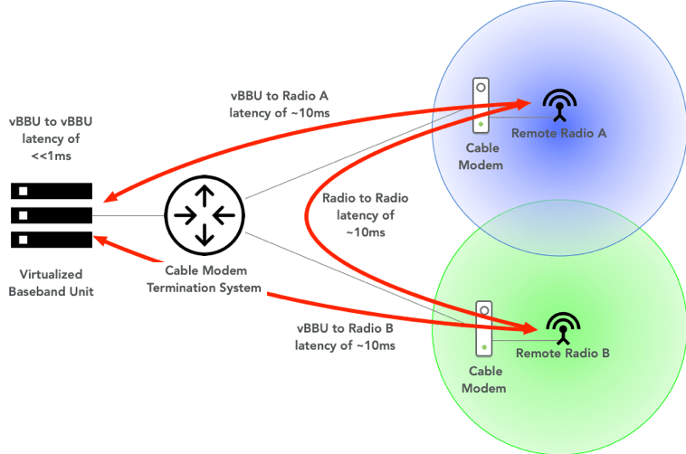
In other words, to realize CoMP gains, the relative latency between a set of cells is more important than the absolute latency from vBBU to each radio.
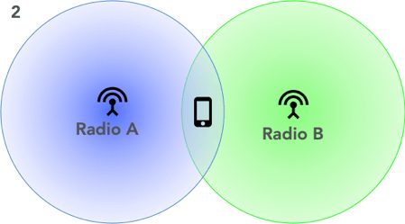
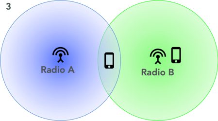
We tested four configurations of phones at the cell center versus the cell edge, or some mix thereof, as the following figure shows.
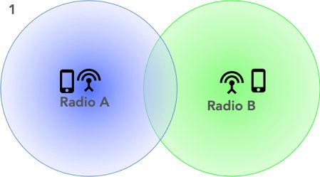
In case 1, we see full cell throughput at each phone with CoMP enabled or disabled. This is great; this result shows that we haven’t lost any system capacity at the cell center by combining the cells into a single physical cell ID (PCI) and enabling CoMP.
In case 2, the phone throughput jumped from 55 Mbps to 78 Mbps when we enabled CoMP, showing a CoMP gain of almost 50 percent.
In case 3, when we enabled CoMP, the phone at the cell edge saw a throughput gain of 84 percent. In this scenario, the throughput of the cell center phone saw a decrease in throughput. This illustrates a tradeoff of CoMP when using legacy transmission modes (TM4, in this case) where the operator must choose whether it wants to favor cell edge users or cell center users. With more advanced transmission modes (e.g., TM10), this tradeoff is no longer an issue. Note that this is true of any CoMP deployment and not related to our use of DOCSIS network fronthaul.
In case 4, we expected to see significant gains from CoMP, but so far we haven’t. This is an area of further investigation for our team.
vRAN Femtocell CoMP in MDUs
Let’s look at an example use case. Cell service in multi-dwelling units (MDUs) can be challenging. A combination of factors, such as commercial construction materials, glazing and elevation, affect the indoor signal quality. As discussed in my previous blog, serving those indoor users can be very resource intensive.
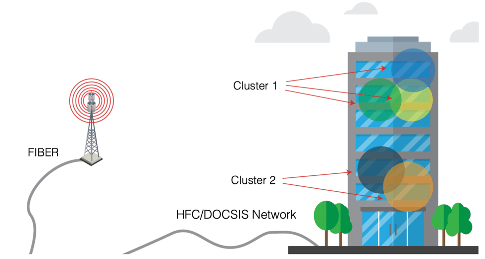
As an operator, it would be great to have a low-cost way to deploy indoor cells. With vRAN over DOCSIS networks supporting CoMP, the operator can target femtocell deployments at heavy users, then build CoMP clusters (i.e., the set of radios that collaborate) as needed to optimize the deployment.
Putting It All Together
The testing described here has shown that CoMP gains can be realized even when using long-latency fronthaul over DOCSIS networks. As these solutions mature and become commercial-ready, deployments of this type will provide the following for operators:
- Low-Cost Hardware: vRAN radios, particularly for femtocells, are low-complexity devices because the majority of the signal processing has been removed and put in the cloud. These radios can be built into the gateway customer premises equipment (CPE) already deployed by operators.
- Low-OPEX Self Installs: With vRAN radios built into DOCSIS CPEs, operators can leverage the simplicity of self-installation. The ability to dynamically reconfigure CoMP clusters means that detailed RF planning and professional installation aren’t necessary.
- High-Performing System: As shown in our testing results, CoMP gains can be realized over DOCSIS network–based vRAN femtocells. This eliminates another of the previous stumbling blocks encountered by earlier femtocell deployments.

Wireless
DOCSIS® Network vs. Fiber Backhaul for Outdoor Small Cells: How Larger Footprint of DOCSIS Networks Lowers TCO in the Outdoor Use Case

In our recent blog post, we talked about how, from a total cost of ownership (TCO) perspective, DOCSIS networks triumph as either backhaul or fronthaul over traditional fiber backhaul for the indoor use case. In this blog, we bring that TCO analysis to a more intuitive, outdoor use case: a head-to-head comparison between TCO of DOCSIS backhaul and fiber backhaul, both of which serve the same set of outdoor small cells.
The basic idea here is: leverage the existing real estate of DOCSIS networks for additional use cases beyond residential/business services. This approach applies to the markets where DOCSIS networks already have a larger footprint than the fiber on the ground. We have seen data points suggesting that there typically is 3~5X more coax cable than fiber in major North American metro markets. This enables a large subset of small cells to be deployed on cable strands or at a short distance from the cable strands, using short drops.
Through primary research, one of our members with dual operations (cable + wireless) confirmed that from a small cell radio planning perspective, they exhaust all cable strand mounting options first, before looking into the gaps for additional sites. This is the key differentiator for DOCSIS technology vs. fiber, where most of the backhaul connections require either new build or premium lease rates.
In this TCO analysis, we showed >50% reduction in TCO for an outdoor use case of backhauling small cells when served by DOCSIS networks compared to a more traditional deployment served by fiber.
But, Is DOCSIS Network the Right Solution for Small Cell Backhauling?
The short answer is – YES.
There are two major requirements associated with any small cell deployment –
- Site acquisition/preparation/construction/powering
- Backhaul with certain capacity/latency/timing synchronization
These two requirements are intertwined since we need to choose a site where backhauling option/s are available and, to the extent possible, cost-effective.
In terms of site (1st requirement) with ready access to backhaul, MSOs have 2 offers on the card:
- Firstly, co-siting small cells with existing MSO owned/operated WiFi hotspots which are already served by DOCSIS backhaul.
- Secondly, leveraging existing cable infrastructure, and in particular aerial plant i.e., cable strands, that takes out a lot of steps (and cost) from the small cell deployment process. Using existing infrastructure eliminates/lightens the need for permitting and site acquisition, preparation/construction and also powering. Along with site access (typically covered by existing pole-line attachment agreements) and power, cable strand deployments also come with readily accessible DOCSIS links as backhaul.
Figure 1 below shows a typical strand-mount small cell installation, consisting of a small cell gateway and a 4G/LTE-A small cell as reported in the technical paper prepared for SCTE-ISBE 2018 Fall Technical Forum by Dave Morley from Shaw Communications Inc./Freedom Mobile. The small cell gateway here contains a DOCSIS 3.1 cable modem and power supply.
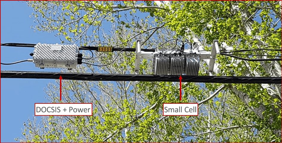
Figure 1: Typical Strand Mount Small Cell @ Shaw Communications Inc./Freedom Mobile
In terms of backhaul specifications (2nd requirement), Belal Hamzeh and Jennifer Andreoli-Fang from CableLabs® have articulated how DOCSIS technologies, with recent developments, fulfills all three fundamental backhaul needs around capacity, latency, and timing in the technical brief titled DOCSIS Technologies for Mobile Backhaul (CableLabs members only). In that paper, the authors have argued that, depending on the mobile operator’s defined SLA, even DOCSIS 3.0 can support backhaul capacity needs. And, significant downstream capacity improvement can be added with DOCSIS 3.1 and significant upstream capacity improvement can be added with Full Duplex DOCSIS.
Regarding latency, control and user plane latency is expected to improve significantly, achieving ~1-2ms latency with the pipelining/Bandwidth Report (BWR) technique across DOCSIS and mobile technologies. Finally, DOCSIS 3.1 already has the mechanism to natively distribute IEEE-1588 timing over the network. With recent CableLabs work on a DOCSIS synchronization specification, DOCSIS 3.1 will also be able to achieve the stringent phase precision as required in LTE TDD/5G networks.
Therefore, in summary, DOCSIS meets the requirements associated with small cell deployment, triggering the need to compare its TCO with traditional fiber based TCO when either one can provide the backhaul for a set of newly deployed small cells in a target market.
Deployment Scenarios We Looked At
For TCO analysis, we considered a hypothetical market covering 100 sq.km. with 290K housing units (HU) and ~700K people in it. There will be 640 outdoor small cells deployed in the market with 150Mbps/50Mbps max DL/UL throughput per cell (20MHz 2*2 LTE cell). For simplicity, using 1:1 mapping between radio and backhaul throughput, we considered peak backhaul capacity of 150Mbps/50Mbps per small cell.
However, since the peak data rates are required/achieved only under ideal conditions, the average DL/UL throughput during the busy hour is much lower, typically 20-25% of the peak rates. We considered the average throughput to be 20% of the peak, thus forming a small cell cluster comprised of 5 small cells that results in 128 total small cell clusters in our market. Each of these clusters is served by a single cable modem capable to handle 150Mbps/50Mbps.
We have 2 identical scenarios: Scenario A, with fiber backhaul and Scenario B, with DOCSIS backhaul, both serving the same market with 128 clusters i.e. 640 total small cells.
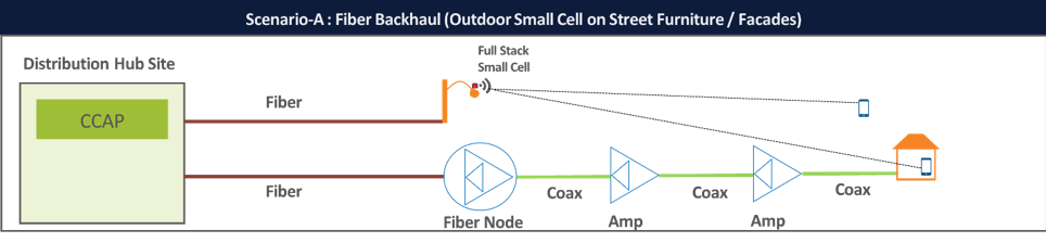
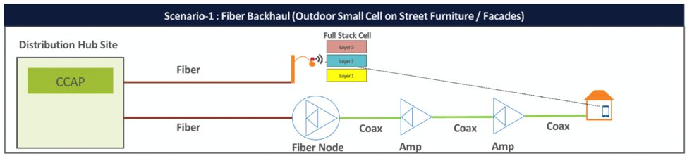
Scenario A: Outdoor small cell served by fiber backhaul
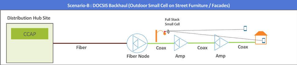
Scenario B: Outdoor small cell served by DOCSIS backhaul
TCO Analysis and Key Takeaways
In this analysis, for both scenarios, we assumed the need for 3 types of backhaul connectivity to bring the small cells online – new build (both scenarios), existing cable strand/MSO WiFi Hotspots (scenario B only), and short drop (~300ft) to site/pole from nearby network (both scenarios).
In our base case, for the 2 scenarios, we applied the following breakdown among types of backhaul connectivity required:
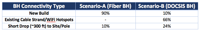
Table 1: Backhaul Connectivity Type Distribution Assumed for Base Case
The distribution of backhaul connectivity type used in our base case is informed based on primary research and market observations. Obviously, there is no one size fits all and this is a key area to assess when an operator analyzes potential TCO savings in a target market. Scenario B’s attractiveness largely depends on the ratio (2/3rd in our base case) of existing cable strand/WiFi hotspots that an MSO can leverage to deploy small cells.
The cost difference between new build and short drop does not come from site acquisition/ preparation/ installation because that need will be identical for both types. However, backhaul lease amount (/month) is different for these two types in our 100% Opex based model for backhaul cost.
Though configurable in our model, our default TCO term is 7 years. Also, we calculated the TCO per user passed and focused on the relative difference among scenarios to de-emphasis the overall cost (in dollars), which will differ by markets, the scale of deployment and supplier dynamics among other things.
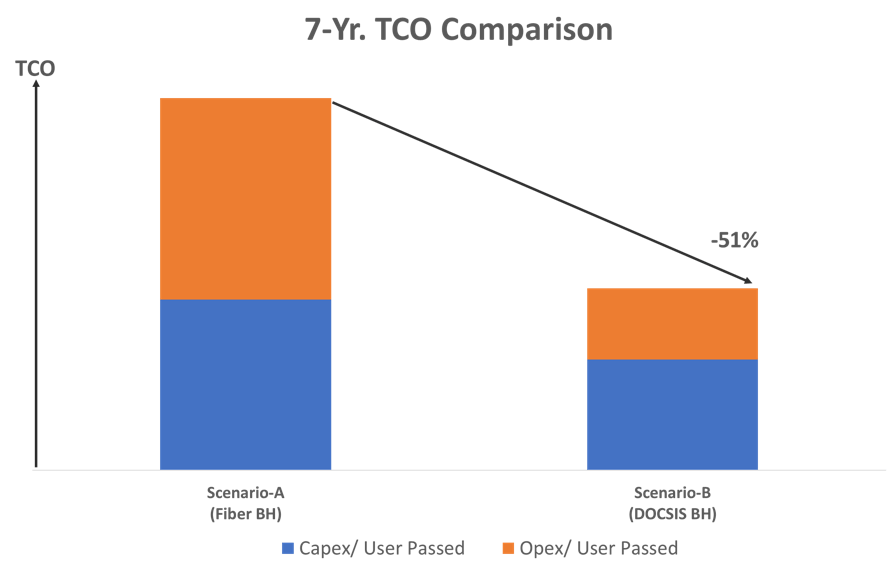
Figure 2: Summary of 7-Yr. TCO between 2 Deployment Scenarios of Outdoor Use Case
According to our base case assumptions, we see the following:
- TCO in DOCSIS BH scenario has the potential to be >50% cheaper than the TCO in fiber BH scenario
- The major difference in TCO between the two scenarios come from Opex. This is because, all 3 key Opex contributors – site lease, site utility cost, and backhaul lease are significantly higher (3~5X) in scenario A than in scenario B.
- There also is a major difference in Capex between the two scenarios. This is largely because, site acquisition/preparation in scenario A costs more (2~2.5X) than the same category of Capex in scenario B, due to the advantage DOCSIS holds for leveraging more existing sites.
- We allocated 20% of DOCSIS network upgrade (from low split to mid split) cost to the DOCSIS scenario. If we take this out (since DOCSIS network upgrades will happen anyway), the Capex associated with plant upgrade cost in scenario B will be gone, making it even more attractive from TCO perspective.
- As mentioned earlier in Table 1, the TCO analysis outcome is primarily dependent on base case assumptions for the distribution of BH connectivity types. If existing cable strand/WiFi hotspots can handle 80% of small cell sites, then, instead of ~50%, the TCO for scenario B will be reduced by ~60%. On the contrary, if that ratio drops down to 50%, then TCO reduction in scenario B will also come down to ~40%.
In an upcoming strategy brief (CableLabs member operators only), we intend to share more details on our methodology, assumptions and breakdown of observed results (both Capex and Opex) along with a full sensitivity analysis.
Conclusion
As we also mentioned in our previous blog (on indoor use case), it’s self-evident that a DOCSIS network-based deployment would have favorable economics compared to a fiber-based model just by virtue of its larger footprint/incumbency alone. When we throw in additional advantages such as lower power requirement/utility charges, that gap only widens. Our TCO model introduced here quantifies that perceived benefit and numerically shows the cost savings in serving outdoor small cells via DOCSIS. This sort of use case strengthens our view that DOCSIS technology has a huge role to play in 5G deployments.
Subscribe to our blog and stay tuned as we continue to explore how to leverage DOCSIS network for mobile deployments. In our next blog post of this series, we intend to look at the DOCSIS networks’ ability to support advanced features such as CoMP.

Wireless
TCO of DOCSIS® Network XHaul vs. Fiber BackHaul: How DOCSIS Networks Triumph in the Indoor Use Case

In our recently published blog post, we demonstrated why indoor femtocells have reemerged as an attractive deployment model. In particular, indoor network densification has huge potential for converged cable/wireless operators who can leverage their existing Hybrid Fiber Coax (HFC) footprint to either backhaul from full-stack femtocells or fronthaul from virtual Radio Access Network (vRAN) remote radio units.
In the second blog in our series, we shift the focus from system level benefits to making the business case. As we walk through our TCO model, we will show a 40% to 50% reduction in Total Cost of Ownership (TCO) for an indoor deployment model served by DOCSIS networks compared to a more traditional outdoor deployment served by fiber. Yeah, that is big, so let’s break down how we got there.
Why DOCSIS Networks?
Before jumping into the TCO discussion, let’s revisit the key motivations for using DOCSIS networks as a tool for mobile deployments:
- Broad-based availability: In a Technical Paper prepared for SCTE-ISBE 2018 Fall Technical Forum, a major Canadian MSO pointed out that there typically is 3~5X more coax cable than fiber in its major metro markets. In the US too, per FCC’s June 2017 statistics, nation-wide cable Household Passed (HHP) stands at 85% (115M units), whereas fiber HHP stands at 29% (39M units)
- Gigabit footprint: As of June 2018, over 63% of US homes have access to gigabit service over cable. In other markets cable operators are pushing ahead with gigabit buildout as well
- Ease of site acquisition: No permitting, no make ready, limited installation effort.
- Evolving mobile-friendly technology: Ranging from latency optimization to timing/synchronization techniques and vRAN support for non-ideal fronthaul links like DOCSIS networks.
Scenarios We Looked At
For TCO comparison, we looked at the following 3 deployment scenarios:
Scenario 1: Outdoor small cell served by leased fiber backhaul
This is the traditional solution for deploying small cells. For our TCO model, we treated this as the baseline.
Scenario 2: Indoor femtocell/home eNodeB served by residential/SMB DOCSIS network links as backhaul.
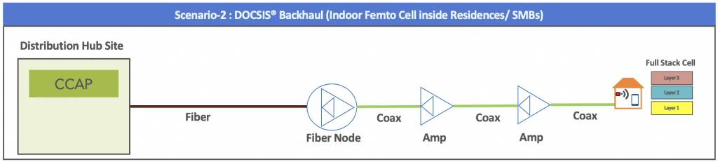
In this scenario, we modeled the deployment of a full-stack femtocell in residential customer homes and small to medium businesses (SMB) served by the converged operator’s DOCSIS network. A converged operator here refers to a cable operator that deploys both DOCSIS network and mobile networks.
Scenario 3: Indoor vRAN Remote Radio Unit (RRU) served by residential/SMB DOCSIS network links as fronthaul
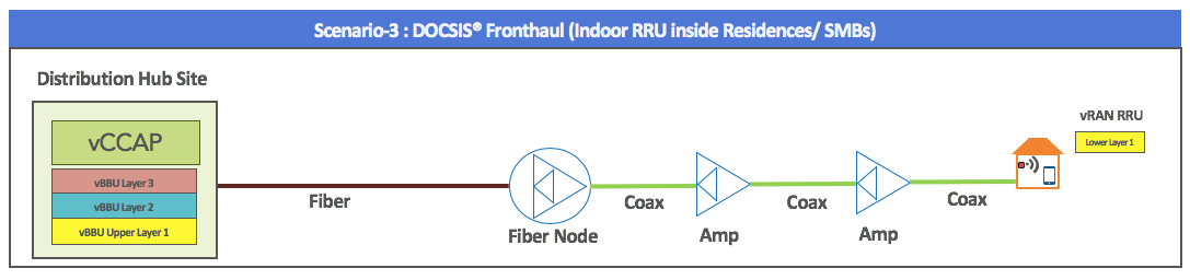
Scenario 3 is essentially scenario 2 but using vRAN. In this case, the virtual base band unit (vBBU) could be deployed on general purpose processors (GPP) servers in the distribution hub site with low-cost radio units deployed in DOCSIS gateways at the customer premise, or SMB location.
Apples to Apples
To build the TCO model, we start with a representative suburban/urban area we want to model. In our case, we used a 100 sq. km area with a total of 290k households (HH). At 2.4People/HH (the US average), our modeled area covered roughly 700K people.
Next, we considered that this area is already served by 10 outdoor macrocells, but the operator needs to boost capacity through network densification.
Under Scenario 1, the operator deploys 640 outdoor small cells that cut existing macro cells’ traffic load by half and boost the spectral efficiency (and therefore capacity) across the network. To create an apples-to-apples comparison of system capacity under all three scenarios, we applied the concept of normalized spectral efficiency (SE) and kept that consistent across the three scenarios. For SE normalization, we added up weighted SE for different combinations of Radio Location-User Location (e.g. In-In, Out-Out, Out-In) in each scenario.
In the end, we used the normalized SE to find the appropriate scale for each scenario to achieve the same result at the system level, i.e. how many femtocells/vRAN radios will be required in indoor scenarios (2 & 3) so the system capacity gain is comparable to the traditional deployment in scenario 1.
Work Smarter, Not Harder
Crucially, converged operators know who their heavy cellular data users are and among them, who consistently use the network during non-business hours, i.e., most likely from their residences. As an example, a CableLabs member shared empirical data showing that the top 5% of their users consume between 25%~40% of overall cellular network capacity on a monthly basis.
So as a converged operator, if you want to prevent at least 25% of network traffic from traversing through walls, you can proactively distribute home femtocells or RRUs to only the top 5% of your users (assuming their entire consumption happens indoor).
In our model, we used the following approach to get the scale of indoor deployment for scenarios 2 and 3:
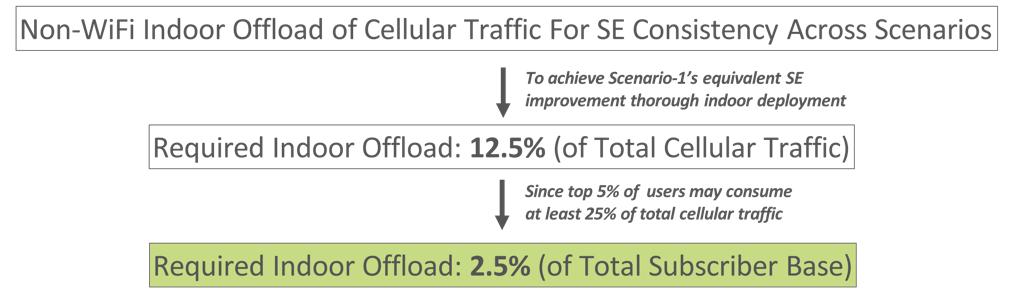
Figure-A: Determining Scale of Deployment for Indoor Use Cases
Therefore, theoretically, if only 2.5% of subscribers start using indoor cellular resources, we can achieve the same SE improvement in scenarios 2 and 3, as observed under scenario 1’s fiber outdoor deployment.
However, we know assuming 100% of heavy users traffic is consumed at home or indoors is unrealistic. To account for a combination of real-world factors including that indoor doesn’t mean only at your residences, that some of those heavy user locations may not be serviceable by a DOCSIS network, and/or some users may opt out from using a home femtocell/RRU we boosted that percentage of the subscriber base we modeled using femtocell/RRU deployments to 12.5% (or roughly 35K units) to make sure that we can definitely capture at least 12.5% of cellular traffic in scenario 2 and 3.
Our Analysis and Key Takeaways
For the TCO model assumptions, we gathered a wide range of input from a number of CableLabs operators and vendors. In addition, we validated our key assumptions with quite a few Telecom Infra Project (TIP) vRAN fronthaul project group’s members.
Though configurable in our model, our default TCO term is 7 years. Also, we calculated the TCO per user passed and focused on the relative difference among scenarios to de-emphasis the overall cost (in dollars), which will differ by markets, the scale of deployment and supplier dynamics among other things.
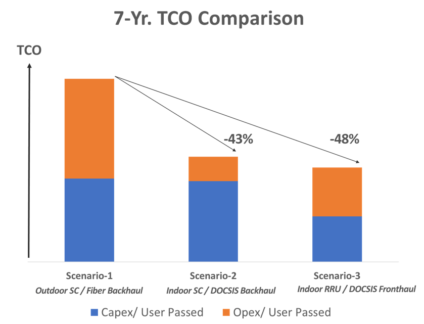
Figure-B: Summary of 7-Yr. TCOs across 3 Deployment Scenarios
According to our base case assumptions, we see the following:
- TCO in scenarios 2 and 3 can be around 40%~50% cheaper than the TCO in scenario 1.
- For scenario 1, Opex stands out as it involves large fees associated with outdoor small cell site lease and fiber backhaul lease.
- Scenario 2 commands a higher Capex than scenario 3, largely because of higher (~2X) unit price per full-stack home femtocell (vs. home RRU) and the need for security gateway, which is not required in scenario 3.
- Scenario 3’s Opex is nearly double (vs. scenario 2 Opex), as it requires a significantly higher DOCSIS network capacity for the upstream link. Yet, notably, despite the increased DOCSIS network capacity used by a vRAN deployment, the TCO is still the most favorable.
- We allocated 20% of DOCSIS network upgrade (from low split to mid split) cost to DOCSIS network-based use cases (scenarios 2 and 3). If we take those out (since DOCSIS network upgrades will happen anyway for residential broadband services) the TCO of these indoor use cases get even better compared to the fiber outdoor case (scenario 1).
- Other key sensitivities include monthly cost/allocated cost of the XHaul, number of small cell sites within a small cell cluster, radio equipment cost, and estimated number/price of threads required for vBBU HW to serve a cluster in the vRAN scenario.
In an upcoming strategy brief (CableLabs member operators only), we intend to share more details on our methodology, assumptions and breakdown of observed results (both Capex and Opex) along with a sensitivity analysis.
What Do These Results Mean?
To us, it was always a no-brainer that a DOCSIS network-based deployment would have favorable economics compared to a fiber-based model. The TCO model introduced here confirms and quantifies that perceived benefit and points out that for network densification, there is a business case to pursue the indoor femtocell use case where market conditions are favorable.
Subscribe to our blog because our exploration of DOCSIS networks for mobile deployments isn’t over. Coming up next we explore a similar TCO model focused on outdoor deployments served by DOCSIS backhual. Later we will shift back to technology as we look at the DOCSIS networks ability to support advanced features such as CoMP.
Wireless
Converged Carriers, Femtocells and Spectral Efficiency: Rethinking the Traditional Outdoor Small Cell Deployment

With the release of any new generation, or “G,” in the cellular world, the goal is always to outperform the previous generation when it comes to spectral efficiency—that is, how many bits you can pack into your slice of airwaves. To telecom nerds, this is expressed as bits per second per hertz (bps/Hz). Going from 3G to 5G, peak spectral efficiency skyrockets from 1.3 bps/Hz with 3G, to 16 bps/Hz with 4G LTE , to 30 bps/Hz with LTE-A, and to a truly eye-watering 145 bps/Hz with 5G (in the lab).
And it makes sense: Spectrum is an expensive and limited resource. Operators pay billions for every MHz they can acquire.
Not What It Seems
Unfortunately, the reality of spectral efficiency in deployed mobile networks is far less stratospheric. A 2017 study pegged spectral efficiencies for a live LTE network at roughly 1 bps/Hz on average with a peak of about 5.5 bps/Hz. So where did all that spectral efficiency go?
The short answer is that it ran smack into a wall. Literally! In 2016, ABI Research Director Nick Marshall said that “more than 80 percent of all traffic [is] originating or terminating indoors,” and we serve the vast majority of that traffic with outdoor cells.
The Inertia of Tradition
In the push toward 5G, we hear a lot about network densification. So far, given the amount of effort going into changing the siting rules, it sounds like the plan is to deploy more outdoor cells to help increase spectral efficiency in 5G networks. In a recent RCR Wireless News article, the headline read “US outdoor small cell antenna shipments to grow by 75% in 2018: Study” citing a study by EJL Wireless Research.
Putting aside the immense issues facing the economics of that approach (more on that in the next blog post covering our TCO analysis), it still relies on an architecture of deploying outdoor cells to handle a largely indoor traffic load. It still puts literal barriers in the way of increased spectral efficiency.
Airtime Perspective
Let’s quantify this issue a bit to make sure we have a shared perspective on the system capacity impact of using outdoor cells to handle indoor traffic because it’s a big deal.
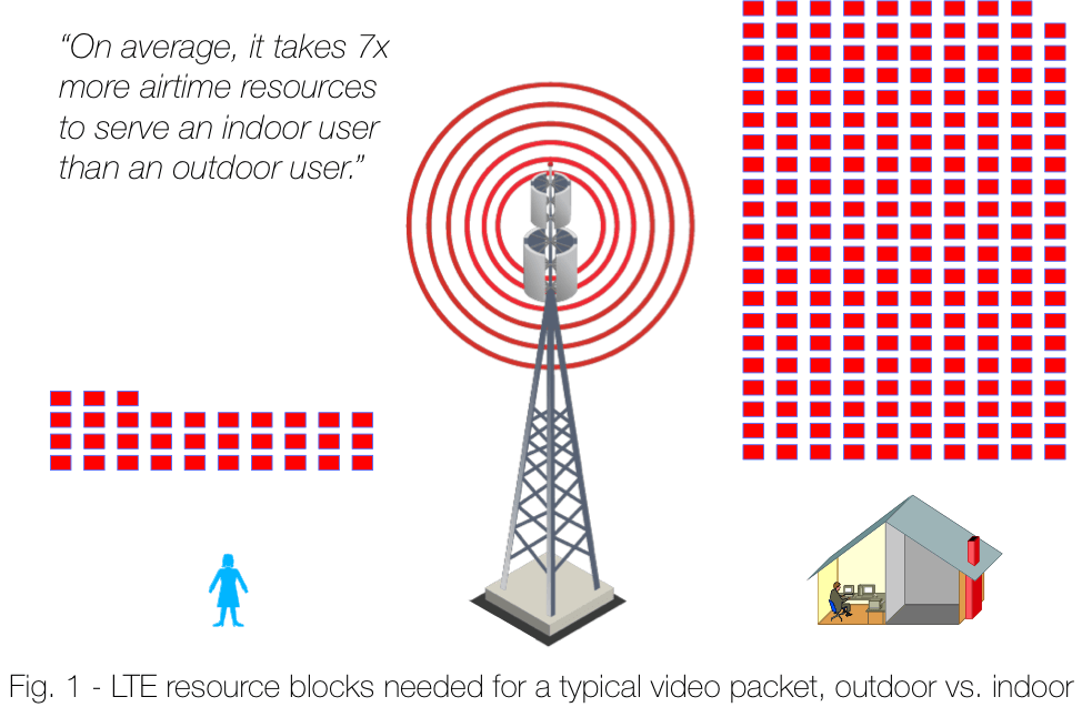
Sending a typical video packet from an outdoor cell to an outdoor user takes 33 resource blocks, whereas sending that same frame to a deep indoor user can take 209 resource blocks (1500B IP packet, I_TBS 3 vs I_TBS 19, TM2 with 2TRx)! On average, it takes seven times more airtime resources to serve an indoor user than an outdoor user.
Given the inefficiency, why are we still trying to cross the walls?
User Behavior
It’s probably not news to anyone that indoor penetration is costly. A common industry view says that when a user is indoors, his or her data should be served by Wi-Fi to offload the burden on the cellular network. Industry reports are produced every year showing that large amounts of traffic from mobile devices are offloaded to Wi-Fi networks (e.g., ~80 percent in 2017).
However, as the industry moves toward unlimited data plans, and as mobile speeds increase, the incentives for seeking out Wi-Fi for offload are diminishing. A recent CableLabs Strategy Brief (CableLabs membership login required) provides empirical data showing that Wi-Fi data offload is declining as adoption of unlimited data plans increases. The trend, across all age groups, shows increased cellular data usage. So as demand for cellular data is going up, an increasing portion is going to be crossing the walls.
There are a number of long-held complaints about the Wi-Fi user experience. I won’t enumerate them here, but I’ll point out that as the incentives to offload data to Wi-Fi are weakened, even the slightest hiccup in the Wi-Fi user experience will drive a user away from that offload opportunity at the expense of your cellular system capacity.
Introducing Low-Cost Femtocells
There’s a growing breed of operator that has both cellular operations and traditional cable hybrid fiber coax (HFC) infrastructure—a big wired network and a big wireless network (Note: here I am talking about full MNOs with HFC/DOCSIS networks, not MVNOs. MVNOs with HFC/DOCSIS networks will have different goals in what optimizing looks like). For these operators, the carrots of convergence dangle in all directions.
Over the past couple of years, CableLabs has ramped up efforts to solve the technology issues that have traditionally hindered convergence. Latency concerns for backhaul or vRAN fronthaul can be resolved by the innovative Bandwidth Report project. CableLabs leadership in the TIP vRAN Fronthaul project is making latency-tolerant fronthaul protocols a reality. Timing and synchronization challenges presented by indoor deployments are months away from commercialization, thanks to CableLabs’ new synchronization spec.
The summation of these projects (and more on the way) provides a suite of tools that converged operators can leverage to deploy mobile services over their HFC/DOCSIS network.
Enter the femtocell deployment model. Femtocells aren’t new, but with the new technologies developed by CableLabs, for the first time, they can be done right. Gone are the days of failed GPS lock, poor handover performance, and interference issues (topics of our 3rd blog in this series). From a spectral and economic viewpoint, femtocells over DOCSIS are poised to be the most efficient deployment model for 4G evolution and 5G cellular densification.
Wi-Fi Precedence
Take Wi-Fi as a guide to how femtocells can improve spectral efficiency. Modern Wi-Fi routers—even cheap home routers—regularly provide devices with physical link rates approaching 10 bps/Hz. That is a huge gain over the sub-1 bps/Hz achieved using an outdoor cell to serve an indoor user. In such a scenario, the benefits are myriad and shared between the user and the operator: The user experience is dramatically improved, the operator sees huge savings in outdoor system capacity, and it all occurs with more favorable economics compared to traditional small cell strategy.
When selectively deployed alongside home Wi-Fi hotspots, indoor femtocells give the converged operator the chance to capture the majority of indoor traffic with an indoor radio, freeing the outdoor radio to better serve outdoor traffic.
More Discussion to Come
In this post, I talked about the spectral efficiency problems of traditional outdoor small cell deployments and how a femtocell deployment model can address them. Next time, I’ll discuss a total cost of ownership (TCO) model for femtocells over a DOCSIS network, both full-stack and vRAN-based solutions.
And don’t take my word for it! Stay tuned to the CableLabs blog over the next couple months for more discussions about cellular deployments over a DOCSIS network.
DOCSIS
vRAN Over DOCSIS: CableLabs Making it a Reality

In November, CableLabs announced the opening of our new Telecom Infra Project (TIP) Community Lab. Today, CableLabs joins TIP in releasing a whitepaper, making public deeper insights into the vRAN fronthaul interface under development in the TIP vRAN Fronthaul project group. With this new interface, the addressable market for virtualized RAN (vRAN) deployment architectures can grow significantly. This increased market is evidenced by the diverse set of use cases being sponsored by the growing set of operator-based TIP Community Labs.
With the release of the white paper, the project group highlights key milestones which have been reached, including agreements further defining the open API and a set of interoperability metrics to be used in validating the interface in multi-vendor configurations.
As the project continues, work on the CableLabs DOCSIS network vRAN fronthaul use case will take place at the CableLabs TIP Community Lab. We look forward to sharing more as we continue to check milestones off our list, so check back soon for updates.
You can find the whitepaper "Creating an Ecosystem for vRANs Supporting Non-Ideal Fronthaul v1.0." here.
Wireless
A Little LTE for You & Me: Build Your Own LTE Network on a Budget

If you’re in a technology role in the cable industry, you’re probably aware that cable is undergoing a tectonic shift from “the future is wired” to “the future is wireless.” Wireless means a lot of things to a lot of people. In the past, wireless meant Wi-Fi if you were talking to a cable nerd. But today, wireless is rapidly shifting to mean mobile, or more specifically 4G LTE and/or 5G. For those of you interested in this wireless future, below, I'll explain how you can build your very own LTE network on a budget.
Time to Tinker
I learn best by doing. Growing up this always terrified my parents. Now that I’ve matured a bit (eh hem), this tendency manifests less as a risk of bodily harm and more as time spent in the lab tinkering. My tinker target as of late has been LTE networks. It turns out there are open source solutions and low-cost parts out there that let you build a simple LTE network (eNB + EPC) for about $1500. I’ve been studying LTE since about 2013, but the last couple of months building and configuring LTE components in the lab have taught me about as much as the prior years combined.
In addition to the great learnings that came from my efforts, we (CableLabs) have ended up with a great tool for research and experimentation. With a cheap and fully open source LTE network we can explore novel use cases, configurations, and deployment architectures, without the need for outside collaboration. Don’t get me wrong, we love collaborating with industry partners here at CableLabs, but it’s great to kick the tires on an idea before you start engaging outside partners. Using this setup, we have the freedom to do just that.
Hardware
The hardware setup is straightforward:
- Two Intel quad-core i7 PCs
- A software-defined radio
- A SIM card
- The UE
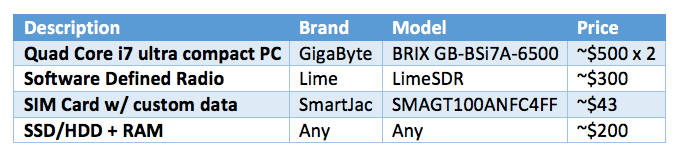
An example bill of materials is below. Replacement of any device with a similarly spec’d product from a different manufacturer should be fine (this list is not meant to be prescriptive or seen as an endorsement).
Software
For both machines, we use Ubuntu as our OS. The LTE system software comes from an open source project called Open Air Interface (OAI). This OAI software is broken into two projects:
- The eNodeB (eNB) called “openairinterface5G”
- The evolved packet core (EPC) called “openair-cn”
Figure 1 shows the LTE functional elements included in each project:
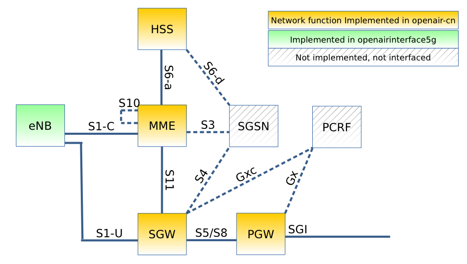
Once downloaded and built you get four executables: eNB, HSS, S/PGW, and MME. With my limited Linux chops, it took me a couple of days to get everything happy and running. But for a Linux ninja, even one with limited LTE knowledge, it can be up and running in a day.
For help getting it going, OAI has a great wiki with a bunch of how-to docs and mailing lists that are quite active. In addition to the great docs on the OAI wiki, do some googling and you’ll see many forum posts and how-to sites around the web, e.g., here is a great tutorial for doing EPC + eNB in a single PC.
It largely works. It’s open source, so the stability is ok, but don’t expect weeks of uptime. Also, note the SGW and PGW are a single executable, so the S5/S8 interfaces are not exposed, even though it’s a solid line in Figure 1. Does this limit your plug-n-play interoperability testing a bit? Sure, but overall the solution is tough to beat for the price.
Another thing to watch out for is UE interoperability. Many phones work, for example, the Samsung S7, Moto G4, but others don’t. LTE has many variations on the attach procedure, but not all are supported by OAI’s EPC currently. But again, it’s free! And it supports some mainstream readily accessible phones, which is pretty sweet.
Other Things to Consider
So we discussed the basics, but there are a couple of other bits you need to line up to get everything working:
- Even though this set up is for tinkering, you will need a plan for regulatory compliance if you want to go over-the-air. For example, in the US you’ll need to contact the FCC to apply for a Special Temporary Authority for the frequency of your choice. Alternatively, you can do all of your testing conducted over cables in your lab. In that case, a UE with external antennas becomes really handy, e.g., the Huawei B593 family of products is what we have used (added bonus that it works great with the OAI EPC).
- You will also need to get some SIM cards. SIM cards are wildly more complicated than I ever realized! My best advice is to go to the experts for help. Gemalto is the tier 1 provider. If you are a tier 1 kinda person, maybe start there. We have also found SmartJac to be super helpful. In either case, I advise starting with the OAI default SIM data set. It will make your initial connection efforts that much easier. Once you get that working, if you want to change the details, you can use a SIM editing software from either Gemalto or SmartJac.
Now do something cool!
Now that you are armed with some knowledge, go forth and make some LTE! Post in the comments if you have questions, want to share your project, run into issues, post in the forums I linked to, or on the reflector… you get the idea…
--
We just announced our new TIP Community Lab where engineers will have access to a bevy of state-of-the-art wired and wireless test equipment. Make sure to read my blog post "CableLabs Introduces New Telecom Infra Project (TIP) Community Lab" for more information and subscribe to our blog to find out about future innovations.
Labs
CableLabs Introduces New Telecom Infra Project (TIP) Community Lab

Today we are excited to announce a new venue for wireless network innovation and collaboration at CableLabs. CableLabs and the Telecom Infra Project (TIP) have opened a TIP Community Lab located at CableLabs’ headquarters in Louisville, Colorado.
What is a TIP Community Lab?
The TIP Community Lab is an integral component of community-based innovation with data-driven results. The goal of a Community Lab is to enable at-scale real-world projects that lead to adoption. These labs provide an open and collaborative working environment for members of TIP project groups to meet, test and refine the solutions they’re developing.
Currently, Community Labs are located at the offices of Facebook and SK Telecom. Today, beyond the CableLabs announcement, Deutsche Telekom announced the opening of its Community Lab in Berlin and Bharti Airtel announced that it is launching a Community Lab based in India.
What goes on at the CableLabs Community Lab?
At CableLabs, we set aside dedicated lab space for the TIP Community Lab. When at the CableLabs TIP Community Lab, engineers will have access to a bevy of state-of-the-art wired and wireless test equipment, including our:
- Channel emulators
- Traffic generators
- LTE and DOCSIS sniffers
- A host of HFC networks we use for lab work
- Various LTE UEs
- Multiple EPCs (LTE core network)
The first project to enter the CableLabs TIP Community Lab is the vRAN Fronthaul project. This project is focused on virtualization of the radio access network (RAN) for non-ideal fronthaul links (i.e. not CPRI). A key component of 5G wireless networks is going to be densification; deploying more, smaller cell sites closer to the users. Think of a small cell site inside your favorite coffee shop, or several small cells peppered throughout the hottest restaurant and bar streets in your city.
The economics of this deployment style don't support pulling fiber links to every small cell, it’s just too expensive. Therefore, a fronthaul technology capable of using “non-ideal” links to connect these small cells (i.e. DOCSIS®, G.Fast, Ethernet, Microwave), can enable new deployment economics.
The Telecom Infra Project
Founded in February 2016, TIP is an engineering-focused initiative driven by operators, suppliers, integrators and startups to disaggregate the traditional network deployment approach. The community’s collective aim is to collaborate on new technologies, examine new business approaches and spur new investments in the telecom space. TIP has more than 500 member companies, including operators, equipment vendors and system integrators. TIP currently has project groups working in the strategic areas of Access, Backhaul, and Core and Management.
CableLabs began participating in TIP a year ago and we now hold a seat on the TIP Technical Committee. We view TIP as a great opportunity for cross-pollination between the different ecosystems that influence the telecommunications networks of the future, and an excellent opportunity to leverage the diverse skills within the TIP community to create new possibilities for end users.
Everyone who has access to 4G LTE today loves how speedy their smartphone is and they want more. They want the speeds that 5G wireless networks promise. But let’s be honest, we want it for equal to or less than what we pay for our service today. TIP is focused on building networks of the future through collaboration that will give operators the flexibility to grow their networks quickly, efficiently and in a cost-effective manner while delivering the 5G speeds users will demand.
In addition, there are more than 4 billion people who are not online. Dramatic improvements in network flexibility and cost reduction would help close this digital divide. To meet these two goals, the industry should pursue new approaches to deploying wireless networks.
Interested?
CableLabs members interested in more information should check out the CableLabs Tech Brief on the topic posted in Infozone (login required). The CableLabs Community Lab is a great opportunity for telecom vendors unfamiliar with cable infrastructure to get their hands dirty with HFC and DOCSIS networks.
CableLabs is also active in other TIP project groups that may come to the Community Lab in the future. For example, we participate in the Edge Computing group. The Edge Computing group focuses on lab and field implementations for services/applications at the network edge, leveraging open architecture, libraries, software stacks and MEC. Contact CableLabs principal architect of network technologies, Don Clarke, if you want more details.
The TIP Community Lab continues the tradition of innovation at CableLabs. So stay tuned, this is just the beginning of exciting news to come from the work going on in the CableLabs TIP Community Lab.
If you got this far and you’re thinking “I want me some of that Community Lab goodness,” join TIP! You can sign up here and get involved. Project groups are open to anyone, operators and vendors, and collaboration is what it is all about and we’re excited to help facilitate.
TIP Summit 2017 - Patrick Parodi - Panel Discussion from sysadmin on Vimeo.
Consumer
Can a Wi-Fi radio detect Duty Cycled LTE?

For my third blog I thought I’d give you preview of a side project I’ve been working on. The original question was pretty simple: Can I use a Wi-Fi radio to identify the presence of LTE?
Before we go into what I’m finding, let’s recap: We know LTE is coming into the unlicensed spectrum in one flavor or another. We know it is (at least initially) going to be a tool that only mobile network operators with licensed spectrum can use, as both LAA and LTE-U will be “license assisted” – locked to licensed spectrum. We know there are various views about how well it will coexist with Wi-Fi networks. In my last two blog posts (found here and here) I shared my views on the topic, while some quick Googling will find you a different view supported by Qualcomm, Ericsson, and even the 3GPP RAN Chairman. Recently the coexistence controversy even piqued the interest of the FCC who opened a Public Notice on the topic that spawned a plethora of good bedtime reading.
One surefire way to settle the debate is to measure the effect of LTE on Wi-Fi, in real deployments, once they occur. However to do that, you must have a tool that can measure the impact on Wi-Fi. You’d also need a baseline, a first measurement of Wi-Fi only performance in the wild to use as a reference.
So let’s begin by considering this basic question: using only a Wi-Fi radio, what would you measure when looking for LTE? What Key Performance Indicators (KPIs) would you expect to show you that LTE was having an impact? After all, to a Wi-Fi radio LTE just looks like loud informationless noise, so you can’t just ask the radio “Do you see LTE?” and expect an answer. (Though that would be super handy.)
To answer these questions, I teamed up with the Wi-Fi performance and KPI experts at 7Signal to see if we could use their Eye product to detect, and better yet, quantify the impact of a co-channel LTE signal on Wi-Fi performance.
Our first tests were in the CableLabs anechoic chamber. This chamber is a quiet RF environment used for very controlled and precise wireless testing. The chamber afforded us a controlled environment to make sure we’d be able to see any “signal” or difference in the KPIs produced by the 7Signal system with and without LTE. After we confirmed that we could see the impact of LTE on a number of KPIs, we moved to a less controlled, but more real world environment.
Over the past week I’ve unleashed duty cycled LTE at 5GHz (a la LTE-U) on the CableLabs office Wi-Fi network. To ensure the user/traffic load and KPI sample noise was as real world as possible… I didn’t warn anybody. (Sorry guys! That slow/weird Wi-Fi this week was my fault!)
In the area tested, our office has about 20 cubes and a break area with the majority of users sharing the nearest AP. On average throughout the testing we saw ~25 clients associated to the AP.
We placed the LTE signal source ~3m from the AP. We chose two duty cycles, 50% of 80ms and 50% of 200ms, and always shared a channel with a single Wi-Fi access point within energy detection range. We also tested two power levels, -40 dBm and -65dBm at the AP so we could test with LTE power above and just below the Wi-Fi LBT energy detection threshold of -62dBm.
We will have more analysis and results later, but I just couldn’t help but share some preliminary findings. The impact to many KPIs is obvious and 7Signal does a great job of clearly displaying the data. Below are a couple of screen grabs from our 7Signal GUI.
The first two plots show the tried and true throughput and latency. These are the most obvious and likely KPIs to show the impact and sure enough the impact is clear.
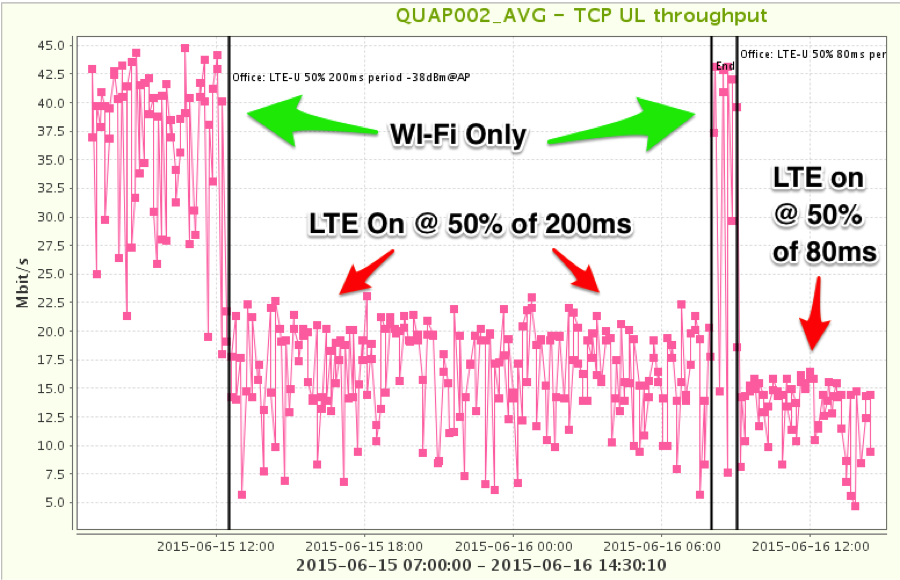
Figure 1 - Wi-Fi Throughput Impact from Duty Cycle LTE
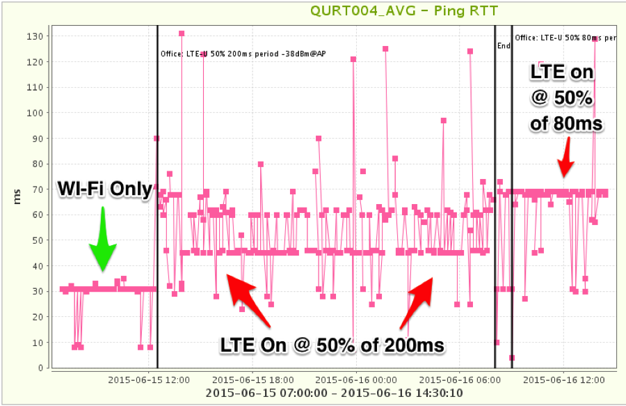
Figure 2 - Wi-Fi Latency Impact from Duty Cycle LTE
We were able to discern a clear LTE “signal” from many other KPIs. Some notable examples were channel noise floor and the rate of client retransmissions. Channel noise floor is pretty self-explanatory. Retransmissions occur when either the receiver was unable to successfully receive a frame or was blocked from sending the ACK frame back to the transmitter. The ACK frame, or acknowledgement frame, is used to tell the sender the receiver got the frame successfully. The retransmission plot shows the ratio of retransmitted frames over totaled captured frames in a 10 second sample.
As a side note: Our findings point to a real problem when the LTE power level at an AP is just below the Wi-Fi energy detection threshold. These findings are similar to those found in the recent Google authored white paper attached as Appendix A to their FCC filing.

Figure 3 - Channel Noise Floor Impact from Duty Cycle LTE
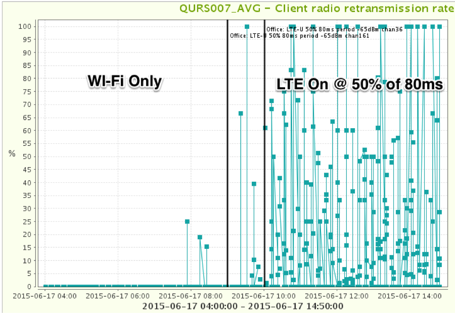
Figure 4 - Wi-Fi Client Retransmission Rate Impact of Duty Cycle LTE
Numerous other KPIs showed the impact but require more post processing of the data and/or explanation so I’ll save that for later.
In addition to the above plots, I have a couple of anecdotal results to share. First our Wi-Fi controller was continuously changing the channel on us making testing a bit tricky. I guess it didn’t like the LTE much. Also, we had a handful CableLabs employees figure out what was happening and say “Oh! That’s why my Wi-Fi has been acting up!” followed by various defamatory comments about me and my methods.
Hopefully all LTE flavors coming to the unlicensed bands will get to a point where coexistence is assured and such measures won’t be necessary. If not — and we don’t appear to be there yet — it is looking pretty clear that we can detect and measure the impact of LTE on Wi-Fi in the wild if need be. But again, with continued efforts by the Wi-Fi community to help develop fair sharing technologies for LTE to use, it won’t come to that.
Wireless
Wi-Fi vs. Duty Cycled LTE: A Balancing Act
In the second installment of my discussion on proposed LAA-LTE and Wi-Fi coexistence schemes, I am going to look at duty cycled solutions.
Let’s recap: We know that this new technology for unlicensed spectrum will be available only to mobile operators since the mobile industry standards body (3GPP) has decided not to pursue the ‘standalone’ version of LTE-unlicensed. (Hence the LAA acronym, which stands for License Assisted Access.) Much of our focus is therefore on ensuring that this new proprietary technology won’t disadvantage other users of unlicensed spectrum, like Wi-Fi. In my last post, I explored the impact of having LAA-LTE adopt “listen before talk” politeness standards, and found that they were not a coexistence panacea. Now let’s cover other politeness approaches.
Different from the LBT approaches discussed last time, duty cycled configurations do not sense the channel before transmitting. Instead, they turn the LTE signal on and off, occupying the channel for some period of time, and then vacating the channel to allow other networks (e.g. Wi-Fi) to access for some time. See Figure 1 for a simple visual of how a duty cycle works.
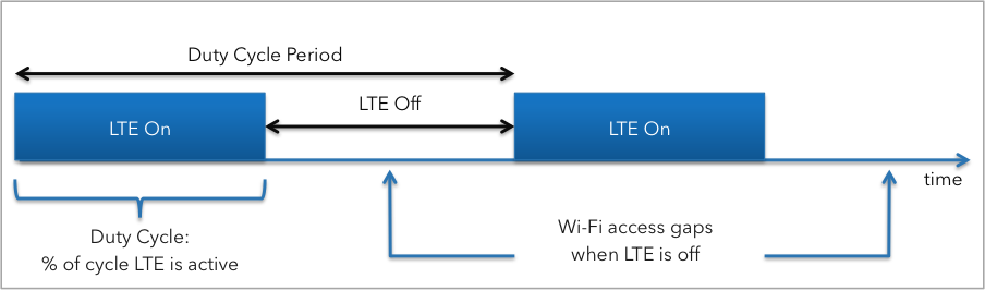
Figure 1
This approach has been proposed by various sources. The first reference we found was from a Nokia research whitepaper, but recently Qualcomm has also proposed an adaptive version they dub Carrier Sense Adaptive Transmission (CSAT) with a flexible duty cycle, while still others including ZTE in their recent 3GPP contribution are suggesting a time domain multiplexing “TDM” (another name for duty cycle) approach.
Duty Cycle %
Duty cycle configurations have two main knobs that define the on and off behavior, the duty cycle percentage and the duty cycle period. Essentially, the duty cycle is a repeating on/off pattern where the period defines how often the pattern repeats (usually in milliseconds for our discussion) while the duty cycle percentage is the fraction of the period that LTE is turned on. See Figure 1 for how these two are related.
Let’s first look at the duty cycle percentage. This configuration knob has a very easy to understand cause and effect relationship on coexistence.
Let’s take an example of Wi-Fi and LTE sharing a single channel. In general, the duty cycle of LTE will define the time split between the two networks because Wi-Fi is a polite protocol that does listen-before-talk (LBT). So if Wi-Fi were alone on the channel, it would get 100% of the airtime. If LTE joins the same channel with a 50% duty cycle, Wi-Fi would now get 50% of the airtime because it would sense the LTE and stop transmitting. In general this means Wi-Fi would get about 50% of the throughput it had in the 100% airtime case.
Now, notice above I said “in general” when talking about the duty cycle percentage? The predictable relationship described starts to break down if the duty cycle period gets really small. So let’s look more closely at the duty cycle period.
Duty Cycle Period
Of the duty cycle proposals described above, a primary difference is the scale of the duty cycle period being proposed. The Nokia Research paper studied the use of almost blank subframes (ABS) or blank uplink subframes in the LTE standard frame structure to produce the duty cycled LTE signal. In either case, the duty cycle period for the Nokia paper is 10 milliseconds.
In comparison, the papers from Qualcomm and ZTE both suggest duty cycle periods of hundreds of milliseconds. Duty cycle periods of this size are likely supported by either the LTE feature called Scell activation/deactivation described here (warning: that link is fairly technical) or the newer release 12 small cell on/off features.
CableLabs Tests Wi-Fi Products
To better understand the effects of a duty cycled LTE signal on Wi-Fi, we did some testing here at CableLabs with off the shelf Wi-Fi products.
First we tested Wi-Fi throughput. For this, we used a wired test configuration where the LTE signal level was above the Wi-Fi clients' LBT threshold i.e. when LTE was on, the Wi-Fi client should sense their presence and not transmit. We then pumped data through the Wi-Fi network and watched what happened as we duty cycled the LTE signal. Figure 2 below shows the results.
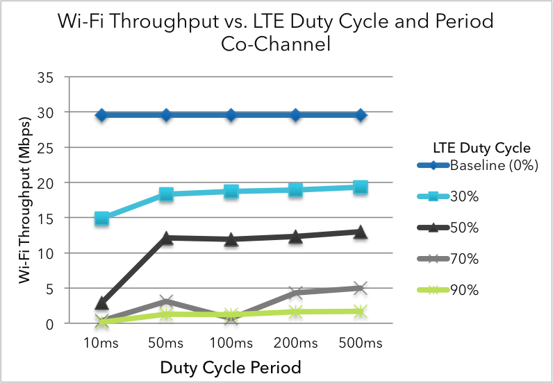
Figure 2
What you can see in Figure 2 is that the duty cycle period has an effect on that nice predictable behavior of the duty cycle percentage discussed above. For the small period case (i.e. 10ms) the throughput performance is worse than predicted.
With a 10ms period, the gaps left for Wi-Fi are too small for Wi-Fi to use effectively.
In addition, because the duty cycled LTE doesn’t do LBT, many Wi-Fi frames that start transmission within a gap get corrupted when LTE starts transmitting before Wi-Fi is done with it’s transmission.
Next we did some over the air testing in our anechoic chamber, again using a duty cycled LTE signal on the same channel as a Wi-Fi network. This time, we measured the delay of packets on the Wi-Fi link, also called latency.
As a quick aside on why latency matters, check out Greg White’s blog post about the recent efforts in the DOCSIS 3.1 project on reducing latency in cable internet services. As Greg points out in his post, user experience for various user applications (gaming, VoIP, web browsing) is heavily impacted by increased latency.
So we looked at latency for the same set of duty cycle percentages and periods. Figure 3 shows the results.
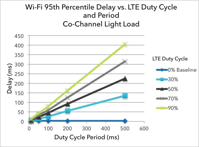
Figure 3
As you can see in Figure 3, as the duty cycle period of the LTE signal is increased, the latency of the Wi-Fi network goes up with it.
With duty cycle periods of a few hundred milliseconds, Wi-Fi users sharing the same channel will see their latency go up also by hundreds of milliseconds. This may not sound much, but as Greg pointed out, an eye-blink delay of several hundred milliseconds could mean many seconds of wait while loading a typical webpage.
The Balancing Act
Based on our testing, it is clear that using a duty cycle approach for LTE and Wi-Fi coexistence is a careful balancing act between throughput and latency.
If the duty cycle period is configured as too low, the throughput of a Wi-Fi network sharing the channel will be negatively impacted. On the other hand, if the duty cycle period is too high, the latency of a Wi-Fi network sharing the same channel will be negatively impacted.
This points to a conclusion similar to our LBT post. While existing options appear to provide some level of channel sharing between Wi-Fi and LTE, there is a lot of work left to do before we see the fair and friendly coexistence solution that Wi-Fi users want. Moreover, the proposed duty cycle solutions offered in recent papers and contributions do not appear to be closing that gap.
Stay tuned for my next post looking at channel selection based solutions and the occupancy of 5GHz spectrum of today and tomorrow.
By Joey Padden -